When the first portable digital camera, recalling in its form a diapositive projector, was built in 1975 by a Kodak engineer, it captured with the help of a movie camera lens, a processor and a sensor an image at a resolution of 100 x 100 pixels and saved it in more than 20 seconds onto a magnetic cassette. (https://imgur.com/gallery/Kl0nI; https://de.wikipedia.org/wiki/Digitalkamera) More than 40 years later a digital camera looks like an analogue one, works in high definition, has a huge storage space and transfers images in fractions of seconds, though the technology has not fundamentally changed.
If we want to understand how the digitisation of a slide with a digital still-camera can be done best, some elementary knowledge on the principles of photography is helpful. So too is some grasp of the basic technical elements of the act. The created files contain basic information about light and colour values: hue (the dominant wavelength from the visible light spectrum, what the eye perceives as the colour of the object), saturation (going from 100% “pure” and vivid colour (no grey) via admixtures (making the colour pale) to zero colour (a shade of grey)) and brightness (or luminance, the luminous intensity of a body) form the material characteristics of the original slide. (For a more academic definition of the three keyword see Poynton 2008, p. 4). (http://poynton.ca/PDFs/ColorFAQ.pdf) A correct recording of all three is the objective of the act of photographic reproduction and the topic of this photographic section. How these values are translated into binary codes is dealt with in the technical sections as they concern both capturing methods (see in “Technical processes” the paragraphs “What is digitisation?” and “The image sensor“) .
“A camera is essentially a light-tight enclosure with a lens at one end and a fitting to take a light-sensitive film or plate at the other.” (Horder 1958, p. 162) Replace “film or plate” by “sensor” in this definition from a popular almost 60 year old photo-book and it becomes evident that not so much has changed between then and now. Cameras got new outfits, and various refinements were added “to make them more foolproof and to increase their versatility” (Focal Press 1973, p. 143), but the principles of photography are still the same: light-rays are sent from an object toward the still-camera in form of waves of different length, frequency and energy; they pass the aperture of the objective, fall through a system of lenses, are regulated in their amount by a diaphragm, the “left-overs” are captured by a light-sensitive device where the rays produce a reaction. As mentioned, the difference between “film or plate” is that thanks to the digital evolution the result of this act can be evaluated almost immediately, the product can be deleted or kept when the expectations are met, and the image can be retouched quite easily if needed.
Today many people take photographs with their mobile telephones (smartphones) thanks to an integrated camera lens and a very small image sensor. But the quality is just what is needed to post them on the internet or mail them to family and friends: its so-called “¼ inch-sensor” (2,4×3,2mm) has a surface of 0,08cm² (Wunderer 2015, p. 17). Although their manufacturers try to make believe that their quality equals a still-camera, these appliances still are mainly tele-phones bridging the spacial gap between people in communication which can be see when “blowing up” the low resolution output. Cameras have components which are specially made to save (otherwise furtive) light impressions and to make them viewable and diffusible in high quality.
Several still-camera types are on the market, each has its advantages and disadvantages. They are different in what they offer (e.g. sensor size, resolution), also in price, flexibility, potential, manageability etc., as they are made for various types of clients and have to meet different needs. If the still-camera has to be used just for immobile objects such as slides (small, flat) or lanterns and accessories (small up to tall, voluminous), if these can be photographed in an (in-house) working space with artificial light, and if all the photographer wants to achieve is to reproduce the objects adequately, then the range of requested elements can be limited, which may make the selection easier.
In the following the most important camera elements will be presented as they can determine the quality of the reproduction: 1. The camera body; 2. The objective, its system of lenses and the depth of field; 3. Diaphragm and shutter; 4. Objectives, focal length and angle of view; 5. The sensor; 6. Viewfinder and LCD-monitor; 7.The image stabilizer; 8.The autofocus, 9.Memory card, storage capacity and bitrate. Also at one point the digital still-camera types are checked whether they fulfil the exigencies.
- The camera body
The first thing the photographer touches is the camera body. In her/his hands it should offer all that is needed to secure a satisfying take: convenience, robustness, small weight to leave more grams for the objective. A body with a solid grip (generally containing the accumulators or batteries) diminishes the risk of camera-shake if the situation asks the photographer to “shoot” without a rigid support. The release should be low-vibration and placed at a spot where the finger finds it immediately and instinctively. An (electronic) viewfinder and a movable liquid crystal display (LCD) should offer two ways to control the take. The body should have easy understandable (“intuitively”) and comfortably manipulable setting dials to select functions and control their “power” (e.g. exposure time, ISO) are a plus as they are quicker to handle than the navigation system on the display of the still-camera with its many sub-sections to click on. An integrated flash is not necessary, the slides are better illuminated by an additional controllable light source. A powerful accumulator guaranteeing several hours of working time, a power supply unit to connect the camera to an external energy supply, and a generally readable high capacity memory card are also welcome. If moving slides have to be taken it may be interesting to check the quality of an integrated video-function in comparison to what real video-cameras have to offer.
| Practical hints given by photographersDSLR cameras (DSLR stands for “digital single lens reflect camera”) are relatively loud when the shutter is released or the zoom is used. This can be really annoying when people work in the same room as the photographer and have to concentrate. A low-vibration release (called “silence mode”) makes less noise. As to the zoom, a helpful invention is the “silent focus”, a motor that focusses in silence. Producers indicate this special technical tool with abbreviations such as USM, SWM, SWD, SDM, HSM, SSM or USD (Gatcum 2014, p. 33). |
|---|
- The objective, its system of lenses and the depth of field
Many cameras are sold with one or more objectives that allow spontaneous switching if the situation changes. If slides are taken with a reproduction stand, the photographer can work with just one objective as the distance between the artefact on a light box and the camera hanging above it is limited by the length of the post. If projection lanterns or other voluminous objects have also to be taken two could be advisable. As the objective is one of the most important elements for a successful reproduction it needs special attention.
An objective is a lens-system made from a number of pieces of special glass: these are ground in different shapes, often attached together with special glue to leave no air between them, normally covered with a thin transparent coating to prevent the loss of light by (uncontrollable) scattering and reflection inside the objective and so as to avoid that the rays end up on the sensor as unwanted light spots. As every lens has its deficiency and can produce aberrations in the form of chromatic, spherical and diffraction errors, producers interfere by combining lenses that balance as much as possible each other’s faults and reduce them “to an acceptable level” (Horder 1958, p. 126). (Sometimes errors are also corrected automatically by the camera’s software.) The optical engineer and specialist in lenses, Hubert Nasse (2008, p. 31), stresses, that the combination of different kind of glass can compensate aberrations such as chromatic ones, but “some residual aberration is still present”. Especially long focal objectives are concerned as “[…] only very recently has it been possible to significantly improve the image quality thanks to the development of completely new types of glass.”
The more lenses, the heavier, longer and pricier the objective. Manufacturers use spherical and aspheric (non-spherical) lenses. “The use of non-spheric lens surfaces can save lens elements […] with the same effective light transmission.” (Focal Press 1973, p. 66) They make the objective less heavy to carry around. The use of aspheric lenses is indicated by abbreviations such as AS, ASP or ASPH while lenses with a special glass avoiding the chromatic aberration are signalised by ED, UD, APO, LD, SD or HLD (Gatcum 2014, p. 33).
The speed of an objective is its capacity to let light-waves reach the light-sensitive unit situated at the end of the “pipe”. It is determined by the maximal amount of light that can fall through the front lens, travel along the diaphragm through the lens-system and reach the image sensor. How much light can hit the sensor is a question of 1. the diameter of the front lens, 2. the widest possible opening of the (iris-)diaphragm, 3. the absorbency and reflection of the lenses, 4. the focal length (FL) of the objective. The “FL” is normally indicated on the objective as e.g. 1:1,4 (for a fixed focal length) or 1:3,5-5,6 (for a flexible zoom lens). These indications signal the ratio between the diameter of the widest aperture allowed by the (iris-)diaphragm (called “entrance pupil”, “effective aperture”) and the given focal length of the objective. Focal length is called the distance between the centre of the lens-system (where the incoming light is concentrated) and the sensor (where the light is send to) when the distance meter of the objective is focussed at infinity (in this position the light rays fall in parallel into the objective). The smaller the so-called “f-number” opposite “1:” the more light can pass through the objective: 1:1,4 means it is powerful in transmitting light, 1:3,5 indicates that its capacity to let light through is limited and that it has a low-light performance. Photographic teacher Anselm Wunderer (2015, p. 77) gives a nice example: a zoom is like a cave, the deeper one enters, the less light is available. An objective which lets much light through its “pipe” is called a “fast” objective, the opposite is a “slow” lens.
Some examples: 1:1 indicates that the diameter of the front lens (e.g. 50mm) and the focal length (e.g. 50mm) are identical and that 100% of the light beam can fall on the sensor (if all the other lenses of the system have the same diameter). 1:1,4 indicates that 50% of the light arrives, 1:2 stands for 25% and 1:2,8 for 12,5% according to Wunderer (2015, p. 76-77).
High-speed “powerful” objectives are a plus as they need shorter exposure times, while “insensitive” low-light performing ones ask for longer shutter openings. This increases the risk that trembling hands produce blurred images when the photographer has to work without a tripod. Release buttons that cannot be pushed smoothly may also cause this adversity. Eventually underexposure occurs which is generally combined with noise. “Noise” looks like little randomly distributed grains; these spots indicate a variation in image density. (For more on noise see Butler, Sanyal 2015.) https://www.dpreview.com/articles/0388507676/sources-of-noise-part-two-electronic-noise
Also a fast objective can cause a problem which lies in its focal length and the maximum aperture of its diaphragm: a too narrow depth of field. The depth of field is called the space before and behind the motive (focussed by the objective) where other elements also appear sharp when everything is depicted together. Photographic expert Tom Ang (2005, p. 225) illustrates the situation with the example of a marching man coming towards the camera which is focussed on a distance of three meters. At first, the man is totally out-of-focus, the more he approaches the three meter-line the sharper he looks, up to the moment when he is totally “in focus”; once he has transgressed this line he gets progressively out-of-focus again according to the decreasing distance between him and the camera. A short depth of field (sometimes inaccurately called “depth of focus”) shows the man in focus only for a short moment, a long one leaves him sharp for a much longer part of his trajectory. The depth of field is determined by 1. the focal length of the objective, 2. the f-number (chosen aperture of the diaphragm, from which the camera then calculates the exposure time according to the light situation), 3. the distance chosen on the distance meter which depends on the object to be depicted (focus distance) and 4. the circle of confusion, also called “blur circle” or “blur spot”. The last concerns what the human eye finds still sharp or already out-of-focus when it checks the reproduction. (Nota bene: Whether something is distinct or indistinct for a viewer depends on the acuity of her/his eye, the distance to the viewed element (a spot which appears blurred when the eye is close may look sharp from a distance) and its size (a small object e.g. on a monitor seems sharp while enlarged it looks out-of-focus). One specific aperture may allow a (deep, long) depth of field area of several meters when the object is at a certain distance, but when the camera is close to the objective the (narrow, shallow) depth of field may only be a few centimetres or even millimetres.
This law is important for the selection of the objective. For an objective with a fixed focal length a small distance can be difficult to handle. Slides are rather flat objects (even those equipped with a moving mechanism), they do not ask for a pronounced three-dimensionality on the reproduction. But when a camera with a 50mm objective and an f-stop of 1:1,4 hangs with fully open diaphragm just one meter above the slide the depth of field is only 2mm according to photographic author Hugo Schöttle (1978, p. 168). If the slide does not lie entirely flat on the light box or the still-camera is not totally parallel to the slide, certain slide parts may be reproduced out-of-focus.
- Diaphragm and shutter
The quality of the objective is highly relevant for the quality of the reproduction. A good lens-system has its price as it should grant excellent definition (“resolving power”) and great speed. A high speed aka “powerful” objective combines two aspects: a diaphragm, which can be widely opened (e.g. aperture of diaphragm of f1,4), and a lens-system, which absorbs only a minimal amount of light; thus it can be used in spaces with few light.
The diaphragm is a ring of small metal parts that form a round pinhole (“iris diaphragm”). It is generally part of the objective and sits behind the lenses. It determines how large the light beam is that enters the objective. Also the diameter of its (maximal) opening is decisive in how far objects, which are situated left and right, above and below the centre of the motive and which are focussed also by the objective, can still be seen (on a display or a viewer) and depicted. An iris diaphragm is flexible in size and be can opened and closed (in so-called “stops”) according to what the photographer needs: more / less light, more / less sharpness due to more / less depth of field.
The diaphragm works in combination with the shutter, both together are responsible for the amount of light which will fall on the sensor. The quantity of photons that reach the sensor depends on the opening size of the diaphragm and the opening time of the shutter. Photographers Tom Ang (2006, p. 215) and John Hedgecoe (2004, p. 13) have found a nice comparison: a water crane fully opened (e.g. wide diaphragm aperture f1,4) will fill a cup with water within a few seconds (short-opened shutter); almost closed (f32) it will take the water a long time until it has filled the recipient (long-opened shutter). The shutter – mostly in form of a sector shutter (a ring of interleaving metal blades inserted between the lenses of the objective) or a focal plane shutter (a metal blind with a slit in the middle put close to the sensor) – has to expose the whole surface of the sensor to light, equally and at the same moment, during a given time. The same quantity of light can be achieved by opening the diaphragm more but for a shorter time or closing it a bit while keeping the shutter open a little longer. An internal light-meter regulates their cooperation automatically. The photographing of a small two-dimensional slides needs a different aperture-time ratio than the take of a three-dimensional optical lantern. The flat (rectangular) slide asks for a harmonious illumination overall by taking a low f-stop to widely open the diaphragm (thus avoiding light refraction at the edges of the glass parts which form the lens-system) while the voluminous apparatus has to be photographed from a distance, with a higher f-number to keep the whole object sharp, and with a light situation that produces (slight) shadows to stress its three-dimensionality.
- Objectives, focal length and angle of view
Objectives can have a fixed or variable focal length. An objective with a fixed focal length cannot vary the distance between the lens-system and the light sensor, the field of view can only be changed when the camera is moved backwards from or towards the item. Objectives of this kind are faster, cheaper in price, and most photography books confirm that they deliver images of higher quality. According to photography expert Chris Gatcum (2014, p. 103) it is much easier to grind lenses for one focal length than to optimize a lens-system with several ones. (Often photographic books talk about lenses instead of objectives, nevertheless lenses are “just” compounds of objectives.) The following information refers to objectives in combination with the widely used full-frame sensor. For larger sensors used in medium format and large size cameras, other focal lengths are valid.
Objectives with a movable focal length (zooms, also called “vario objectives”) are variable as they have more than one focal length, due to lens groups inside the zoom which can be moved for that effect. Just by turning the zoom’s tube the field of view can be made smaller or broader. Their advantage: the great flexibility allows to photograph with one objective (small) objects directly in front of the camera and also those which are far away. Their disadvantage: they show a low-light performance, are heavy and relatively voluminous.
| Practical hints given by photographers
Some cameras with a fixed focal length advertise a zoom function. Julia Adair King (2017, p. 44) advises to check whether it is a “digital zoom”: the so-called “digital zoom” is a software function which asks the sensor to “zoom in” a segment of the taken image by cutting its edges and enlarging its centre. According to King this decreases the image quality. Only a vario objective has a real “optical” zoom. |
|---|
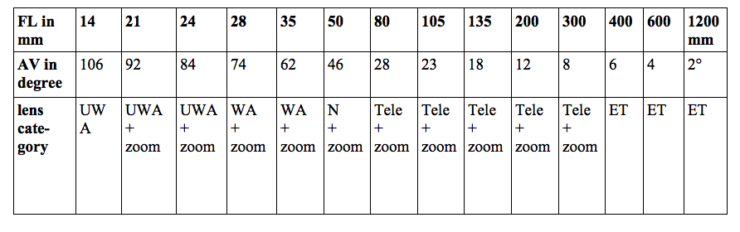
Not only the f-number, also the so-called “angle of view” has to be taken into account when choosing an objective. The angle of view is “the amount of the subject included in the negative” (read here: in the digital image) (Ilford 1958, p. 84); it changes with the focal length of the objective. The higher the focal length (FL) the smaller the angle of view (AV).
Photographer Tom Ang (2005, p. 222) has found a good comparison to explain the relationship between the focal length and the angle of view. He suggests to imagine looking through a hole in a fence: when the eye is close to the hole is sees (almost) the whole landscape behind the fence (large angle of view with a short focal length: wide angle objective). From a certain distance to the fence the eye just sees a part of the motive behind the barrier (narrow angle of view with a longer focal length), and this part looks rather small. A long-focus objective does a combination: it shows the small sector that the eye can see through the hole from a distance to the fence, but this part of the landscape is enlarged as if it was seen with the eye next to the hole. A zoom can switch from focal length to focal length (variable distance to the fence): it “zooms” in and out of the landscape, and when the optical system approaches or withdraws from the object it changes the size of what can be seen “through the hole”.
As slides have different formats it is necessary to choose an objective with an adequate angle of view leaving not too much space around the slide (e.g. toy slides are 2-4 times wider than high, but also some specimen for professional use can be extensive in width and very limited in height). It is extremely time-consuming and also tiresome in post production to crop each digital image to eliminate the topic’s unwanted surrounding also visible on the picture. Nevertheless, it is indispensable to downsize the amount of pixels (e.g. for restricted storage space – why keep more pixels in a proxy than necessary – or aesthetic reasons etc.) and to concentrate on the essential (e.g. the slide’s image, an original labelling, a manufacturer’s logo), especially when the reproduction is used e.g. in a publication or online. A proper aspect ratio of 1:2 to 1:4 would be suitable, but would ask for an ultra-wide angle (“frog eye”) which cannot be used because it would deform the image of the slide.
The following overview is taken from the books by Tom Ang (2006, p. 223) and John Hedgecoe (2004, p. 39) but the information can also be found in others, sometimes with slightly different figures. An angle of view refers not to the horizontal width of the taken image, but to its diagonal (which is a bit longer). The indicated degrees of vision beneath correspond to the focal lengths of a still-camera using a full-frame sensor (24×36 mm) which corresponds to an aspect ratio of 1:1,5 (or 3:4 in video camera talk). “UWA” stands for ultra wide-angle, “WA” for wide-angle, “N” for normal focus, “ET” for extreme-long focus.
4.1 The characteristics of lens-systems
For the reproduction of slides which are not very variable in dimension and therefore do not ask for a quick change of focal length, it could be convenient to choose just one objective with a fix focal length. For voluminous objects such as lanterns, fix and movable objectives could be practical. Every type of objective is designed to meet specific needs; for that reason the mission of the digitising project and the operation method have to be know beforehand.
- “Normal” focus objectives (fix focal length: 45 – 50mm) are supposed to imitate the human vision. Tom Striewisch (2009, p. 87) states that images taken with this focal length reflect the impression a person would have in the same situation. This lens-system is “suitable for subjects which are not normally regarded with very great attention” (Ilford 1958, p. 87). Its maximal opening is generally an aperture of f1,8 (Freeman 2004, p. 76). Objectives with focal lengths that are shorter are called “wide-angles”, longer ones are “teles”. “Normal” focus objectives can be made quite flexible with the aid of extension rings, a bellow or a close-up lens which allow to approach the object to depict details.
- “Wide-angle” objectives (fix focal length: 28 – 35mm) have a “broad view” on the object, they reproduce more of the surrounding and have an impressive depth of field, but, as more is to be seen, it reproduces the single object in smaller size. Wide-angle lens-systems have a large diaphragm aperture and are faster than “normal” objectives due to the short distance between frontal lens and sensor which the light beam has to cross. However the captured light rays can get lost progressively towards the edges of the lenses – an effect called “vignetting” (see Schöttle 1978, p. 210, 300) – which makes a uniform illumination of the sensor difficult if the combination of different lenses does not correct this flaw optically with differently grinded lenses, or with the help of automatic software. A wide angle objective is more expensive than a normal one due to a higher number of glass lenses and a more difficult structure.
Objectives with an even shorter focal length (15 – 24mm) are called “ultra wide-angle”. They cover even more of the motive but we would not recommend them for slide reproduction as they easily produce distortion at the edges of the image (due to vignetting), and the slides appear unnatural as their look is distorted.
- “universal zoom” objectives (variable focal length: 15 – 300mm or more) are highly flexible, they can be used to take the whole slide or just a little detail from its surface in close-up. As a zoom can produce many different focal lengths (according to its size between e.g. 28 – 80mm, 35 – 105mm, 70 – 400mm) the advantages are considerable: e.g. no changing of objectives (and thus no risk of dust on the sensor), always and everywhere ready to take a picture, only a small number of accessories to carry around. But the shortcomings are quite annoying: smaller maximum aperture of the diaphragm and thus a lower light performance compared to others, more expensive than an invariable objective (however no need for a second one) and heavier due to a greater number of lenses (at times up to 20). Photographer Michael Langford (2008, p. 94) indicates c. 500g for a 80mm glass objective, but for a 100-200mm zoom certainly c. 2.200g. (Today lenses are also made from lighter plastic and may be as good as glass lenses according to the professional photographic business, but they are less resistant to scratches). Next to a narrow depth of field, the biggest disadvantage is the decreasing speed: the longer the tube, the smaller the amount of light falling on the sensor (thus a high risk of noise). The maximum opening of its diaphragm is generally f3,5 or f4,5 (Freeman 2004, p. 76). A take requires a longer exposure time, and, as most zooms are heavy, this can lead to a blurred image due to trembling hands. It then becomes necessary to use a tripod (which at least can be carried around) or a camera-stand (which normally imposes a fix location). Furthermore, it seems that zooms which offer many different focal lengths are less sharp than those which cover just a limited range.
- “macro” objectives (fix focal length: 15 – 200mm) enable the viewer to approach the object and make close-ups. If the reproduction scale is 1:1 it means that a small object (e.g. a detail on the slide) can be reproduced in its original size (1cm in the original = 1cm on the sensor), if the ratio is 1:2 it will be reduced (1cm on the sensor’s surface corresponds to 2cm on the slide’s surface), but it can also be enlarged. With a standard macro objective (FL 50mm) the optimal working distance between camera and object for a 1:1 magnification is c. 20cm; a focal length of 90mm or 100mm (short telephoto) is useful for an interspace of 30cm; when a interval of 50cm should be bridged a long telephoto with a focal length of 150 or 180mm is most suitable (see http://ilovehatephoto.com/2015/04/13/choosing-the-ideal-macro-lens-focal-length/). Most slides will not require the last size. A long objective is quite heavy and costs a lot more than a short one, but it allows to work at a greater distance to the slide which may make its illumination easier.
The other variations – “long-focus objective” (focus length: 135 – 300mm) or “extreme long-focus objective” (focus length: more than 300mm) – are not practical for slide reproduction as they are made for outside photography (Freeman 2004, p. 30-31). As they work like a telescope they approach and enlarge objects that are far away, but their angle of view and their depth of field are quite small. Extreme long focal objectives make the reproduction look quite unnatural. (Also viewfinders are not usable for objectives with a short or an extremely long focal length (Striewisch 2009, p. 24)).
To resume: For the reproduction of slides an objective with a focal length between 28 (wide-angle) and 80mm (zoom) seems appropriate. A “normal” focus objective would be convenient to photograph a voluminous object as it demands a longer distance between camera and object than a slide on a light box. With a zoom lens both situations can be handled. As the light intensity decreases with the increase of the focal length it could be considered to work with two fixed objectives (wide-angle, normal) or a wide-angle objective for the slides and a zoom for the rest. A camera can be brought nearer to an object by adding an extension tube or a bellow (both put between the objective and the camera body) or by adding a close-up lens in front of the objective which functions like spectacles or a magnifier (the latter seems to be of lower optical quality according to Freeman 2004, p. 216). (For more see section “The digital still-camera’s accessory “equipment”).
| Practical hints given by photographersSome photographic experts suggest that it is better to use a wide-angle or a normal objective and approach the object than to use a zoom. Photo-journalist Armin Smailovic titled his article: “Movement makes the best photograph” (“Bewegung macht das beste Foto”, Zeit Fotografie, 8.5.2017, p. 39). For the reproduction of objects they advise to combine only objectives from one producer as these have the same little “colour fog” (tint) which, when known, can be corrected quickly in post production when considered disturbing (e.g. the image is not faithful in colour to the original). |
|---|
| Practical hints given by photographersWhen changing the objective, dust in the air can fall on the sensor. Several photographic books recommend when switching lenses to do the change quickly and in a space free of dust. Lenses have normally an antistatic coating, but dirt cannot be avoided totally and small particles that get on the lens will be reproduced as white dots. To reduce this risk, the camera should be directed towards the ground (National Geographic 2007, p. 59).
Tom Striewisch (2009, p. 352, 73, 75) recommends to control whether particles have fallen on the sensor as they leave traces on the image. He suggests closing the aperture and directing the objective onto a white surface (e.g. wall) which should be photographed. If the photograph examined on the computer monitor shows black dots (as no light has got through to this part of the sensor), dust sits on the sensor. It can be removed very carefully with compressed air from a little rubber bellow; in any case, the indications and instructions given by the manufacturer have to be followed. Even if an in-built automatic anti-trilling system theoretically deals with the problem when the camera is switched on, it is wise to control the cleanliness as this automatism is no guaranty that all the particles are gone. Other recommendations are given by Dennis P. Curtin (2011, p. 22). |
|---|
- The sensor
Pixels are the smallest information unit of an image. They can be square or rectangular, are arranged in a two-dimensional array, and all together, like parts of a puzzle, they form the picture as each pixel contains information needed for the accurate reproduction of a slide. This arrangement is due to the small sensitive units (“photo-diodes”) on a sensor which are also called “pixels”. One could call them image pixels and sensor pixels to better distinguish them from the screen pixels a monitor works with.
5.1 The sensor models
Scanners normally have a CCD sensor in form of a long small row which registers a slide progressively (“line-scanning”); the lines are then combined and form a two-dimensional image. Still-camera sensors are square or rectangular surfaces (“matrix CCD”) and reproduce a slide in “one shot” (“area-scanning”). While the first method is considered “one-dimensional”, the other is seen as “two-dimensional”.
A CCD or a CMOS sensor in a still-camera function like their “siblings” in a scanner (see “The construction of the sensor” in the technical section). In addition, one photographic manufacturer has created the “Foveon X-3 sensor” which imitates the well-known red, green and blue colour layer system of the traditional film stock. The so-called “Foveon-chip” reminds photographer Eib Ebelshäuser (2005, p. 228) of the analogue film material: the sensor is built of three silicate layers, each with photo-diodes sensitive to another colour; the upper one captures the blue waves, the next the green ones, and the lowest level gets the remaining red portion of white light. As with film material the basic idea is that different light-waves penetrate silicon (the material semi-conductors are built of), but not equally deep (Striewisch 2009, p. 40), some get stuck earlier than others. In each layer a grey image is formed out of light values (“colour separation”) (for more information see “The image sensor” in the technical section). The size of a photo-diode is about 7 microns. (https://en.wikipedia.org/wiki/Foveon_X3_sensor)
Today most digital still-cameras have a CMOS sensor. As the CCD variant, it works with a Bayer mask. Such a sensor captures different amounts of light-waves: 50% of green, but only 25% of each blue and red. By interpolation the camera processor adds respectively 25% of red and blue values (see “Colour capturing and Bayer mask” in the technical section). These camera models produce about half of their pixels mathematically, thus their pictures contain a lot less colour information from the original slide than those taken with a Foveon “X3-chip”.
The difference between both systems is: Foveon sensors put the information in stacked “subpixels” (i.e. sub-picture elements, the three sectors of a Foveon pixel) while CCD and CMOS put them adjacent and in little groups of four. A Foveon photo-diode receives all the information on colour while a photo-diode on a CCD and CMOS sensor, working with a Bayer mask, has just details about one, depending on the filter which covers its front: green or blue or red (for more see “The image sensor” in the technical section). (For a practical comparison between the two systems see http://www.ddisoftware.com/sd14-5d/).
5.2 Sensor size and resolution
The quantity of pixels on a camera sensor is indicated in “megapixels” (MP) signalling the totally of all photo-diodes, the amount normally being rounded up. Digital single lens reflex cameras (DSLR) are mostly equipped with a CMOS sensor of c. 12 – 42 MP and a photo-active field of 35,6 – 35,9mm width and 23,8 – 24mm height (reminding the size of the analogue still-camera negative frame of 36x24mm on a 35mm-gauge) in a ratio of 3:2. Other cameras offer a smaller light-sensitive surface, e.g. 17,3 x 13,0mm (called Four-Thirds) with an aspect ratio of 4:3 and in total 21,77 MP, of which 20,30 MP are “camera effective pixels”. As not all photo-diodes on the sensor are really working, the amount of pixel is given in “effective” and “total” pixels. Photographer Tom Striewisch (2009, p. 40) estimates that only 60 to 70% of all pixels are working. Before the term “megapixel” was used for computer monitors (where this annoying problem occurred) and indicated the theoretically possible amount of pixels.
More important is the camera’s capability to reproduce small details (“optical resolution”). In the time of the analogue film camera “resolution” meant a film’s potential to show distinctly a certain number of dark and bright lines next to each other on a surface of one millimetre. One pure black and one adjacent clear line formed a couple which was expressed in “lp/mm”, i.e. line pairs per millimetre (thus 20 lp/mm meant 40 line widths per millimetre). This potential depended on the speed of the emulsion based on the size of the silver grains it contained, and also on the characteristics of the lens-system. (Interestingly, the line pairs for film were often thought of on a horizontal line, while in the digital universe 20 lp/mm is understood as measuring staff applied vertically: 20 line pairs per millimetre sensor hight.) (For more information on resolution see sections “ Technical components of digitising an artefact and The resolution”.)
A sensor’s reproduction quality is a combination of the amount of pixels and the size of the pixels. Years ago a video sensor with Digital Light Processing (DLP)-technology and a diagonal of 35,1mm had already 9 million pixels with left each pixel a space of about 57μ² (square microns). Today 36,4 MP (with 24,3 MP or even 12,2 MP effective pixels) on a “full format”-sensor (24x36mm, diagonal 43mm) are normal (Sony 2016, p. 16, 22). There is no given correlation between the number of megapixels and the size of the sensor. The more pixels are crammed on a surface of the same size, the smaller the surface of each unit to capture light, the more gaps between the photo-diodes where light is lost as it cannot be captured. Thus more pixels does not mean a higher image quality. In his book photographic expert Anselm Wunderer (2015, p. 14-15) states that compact cameras put some 16 megapixels on c. 0,29cm² which leaves each round pixel a surface of “1,4 and 1,3μm”. To give an idea: a human hair has a average of c. 50 micrometres and is thus 38 times bigger. In his book digital expert Tom Bert (2011, p. 218) shows that the width of a human hair “would cover more than 40 lines or colons” on a ordinary sensor.
The amount of pixels seems “limitlessly” increasable, and their size is quite variable: Anselm Wunderer mentions a full-frame sensor (8,64cm²) with 50,6 MP. Compared to those of compact cameras, its pixels are definitely larger but still “small”: 4,1μm (micrometer), while another sensor of the same size, but with 16 MP, has really “big” ones in 7,3μm (Wunderer 2015, p. 34) or even 8,5μm for one with 12 MP (Nasse 2007, p. 3). The expert insists that “bigger pixels ‘see better’ and can better distinguish between brighter and darker parts of the image” (p. 15) which results in a higher image quality. On the other hand, the bigger the pixel (some are more than 20µm long), the less can be put on an ordinary sensor as 36 x 24mm is the biggest size for a normal still-camera. The pictures may have light and colour values that are truer to the original ones on the slide, but as the resolution is lower, less details can be reproduced in all their finesses. Therefore, the real resolution of a camera sensor is not identical with the MP value indicated by the manufacturer, and a high amount of megapixels is thus not per se a sign of excellency.
5.3 Optical system, sensor, amount of photo-diodes, size of pixels and sharpness of the reproduction
The camera’s potential for sharply depicting the details of the original depends on two factors: the sharpness (resolution) of the lens – its “ability to discern fine details in an image (D’Amato 2000) – and the resolution of the sensor, i.e. the total number of pixels on its surface (the sampling frequency of the sensor). IT-specialist Donald D’Amato calls the first the “spatial resolution” (the higher, the sharper the image) while Dennis P. Curtin (2011, p. 9) refers to the second as “pixel count”; both are practical for distinguishing well between the two kinds of resolutions. Lens systems, even in the best objectives, blur images to some extant, e.g. due to optical diffraction (light bending) and diffusion produced by lens aberrations. Therefore photographer Eib Eibelshäuser (2005, p. 248) insists that the optical “resolution” of the objective (the camera’s spatial resolution) has to be at least conform to the resolution (aka the “pixel count”) of the sensor. He requires a sophisticated lens-system that corrects the imperfection of each polished glass. However, the reproduction’s sharpness and being in-focus not only depend of the objective’s “subtlety”, but also e.g. of “contamination of the sensor or optical elements, vibration in the document transport mechanism, electronic noise introduced before analog to digital conversion” (D’Amato 2000) etc. This point will not be discussed further.
As to the sensor, the amount of pixels is just one aspect, the other is the size of the light-sensitive units that are “squashed” on the chip’s horizontal rows: the more photo-diodes are fixed on one inch, the smaller they are and the less light each receives. Tom Striewisch (2009, p. 335) has found a nice metaphor: the more buckets have to be put on a surface, the smaller they need to be and the less drops each will catch during a rainfall. If the pixels receive less light, the received optical signal has to be amplified and will add to the (background) noise which every electronic device produces. Today the industry proudly presents up to 50 megapixels on a sensor, but it does not contain information about the size of the photo-diodes. With the following formula given in a discussion forum (and repeating an information given by Canon), it can be calculated: “Determining pixel dimensions from sensor width & height: If you are told the actual dimensions of the sensor, determining pixel area is simple [*=BY]:
Area of entire sensor (in mm2) = width in mm * height in mm
Area of entire sensor (in µm2) = 1,000,000 * area in mm2
Area of one pixel = area of sensor in µm2 / # pixels.” (https://blenderartists.org/forum/archive/index.php/t-338201.html)
Applied to a full-frame sensor this means: 24mm x 36mm = 864mm² x 1,000,000 = 864,000,000 : 36MP (36.000.000 pixel) = 24µm2. One pixel on a full-frame sensor with 36MP covers a surface of 24µm2. With 12 MP on the same surface one pixel is much bigger, its size is 72µm2. The opening of the “bucket” is almost three times bigger. It seems that sensors with fewer, but larger pixels on one inch are superior as they not only capture more light, but are also further away from each other and the “dark area” around could be bigger. The question is: could this help against infecting neighbouring dark pixels with energy, and maybe even against “charge hopping”? On the other hand, more pixels will allow to better reproduce round objects as they smooth the curves: “As more pixels are added, edges become more refined and the shape becomes more like the original.” (Curtin 2011, p. 9) (www.photocourse.com/itext/pixels/pixels1.pdf )
The amount of pixels determines the resolution (how many “samples” are taken from the original object per counting unit, i.e. inch or cm), while the format of the sensor and the size of a pixel is one of the factors responsible for sharpness: “Larger image sensors generally have larger photosites [pixels] that capture more light with less noise and a greater range of tones for smoother transitions. The result is pictures that are clearer, brighter, and sharper. Because the size of photosites is so important, a large 8 Megapixel sensor will often take better pictures than a smaller 12 Megapixel sensor.“ (Curtin 2011, p. 15)
What is sharpness? It determines how many small details can be see. The higher the sharpness, the more they are clearly visible. The human eye reacts to contrast: the higher it is between two zones of different colours or tones, the better the eye sees the edges of each, thus the boundary between these areas and identifies them as two separate units. (For more information on sharpness see e.g. http://www.imatest.com/docs/sharpness/) Sharp means that a couple of two parallel lines, formed by one in black and the neighbouring one in white, are reproduced as two distinct units. This rule was already in use with analogue photography and movie projection. The sharpness of a lens-system (its “resolving power”) can be measured by analysing the amount of lines per distance that are clearly visible when looking or projecting through the objective. In former days, movie projectors were tested using loops with a fine bar pattern to see whether the totality of the projected image was sharp. If the boundaries between the lines appeared gradual and not firm on the screen, the image was blurred.
When a lens-system causes blur, the contrast is decreased in the reproduction. However, sharpness is also a subjective feeling depending on the specific characteristics of the eye of the beholder, the composition of the depicted (soft or hard contrast), or the lighting circumstances under which the image is regarded (white strong directed light, half darkness) and, according to Nasse (2009, p. 8), even the motive you look at. Some people may feel that something is sharp, while others think it is blurred, that they are missing image information.
According to Eib Eibelshäuser (2005, p. 248) and Hubert Nasse (2009, p. 6), at least two pixels are needed to allow this traditional measurement of sharpness: one for the dark and one for the clear line. As already stated: more pixels mean a higher sampling rate and more details that are captured on the sensor. Besides the effect that lens-systems always blur a bit which effects the slide’s reproduction on the sensor, its capacity to produces sharp images is also influenced by its electronic nature: the more noise due to more MP on the same surface disturbs the impression of sharpness. But also the camera’s construction can interfere: an anti-aliasing filter which are built in in compact and DSLR cameras to avoid the danger of moiré is fixed just before the sensor. Retouching specialist Matthias Matthai (2008, p. 52) stresses that this tool always produces slight blurring.
A last point has to be mentioned here: the impression of sharpness also depends on the size of the reproduction and the standpoint of the viewer. The printing of a poster requires a relatively low resolution (e.g. 60ppcm/152 dpi (= 152 dots per inch) for posters between 70x50cm and 90×67,5cm, see e.g. https://www.myposter.de/magazin/aufloesung/) as it is seen from a certain distance (c. 100-200cm) while a person in front of a computer (c.50cm and less) who approaches the monitor or even zooms into the image will need a much higher resolution to identify the depicted as “sharp”. Also the angle of view can make a difference in sharpness.
To resume this point: the quality of the objective, the size of the sensor, its resolution and the size if its pixels as well as the construction of the camera (capture situation) determine “physically” how sharp the slide will be when its visual qualities are preserved as a file. Therefore, the highest quality of the technical elements is required. As Dennis P. Curtin (2011, p. 6) states: “If you think one film gives images that are too blue or red, you can change to another film although choices are growing more limited. With digital cameras, the “film” is permanently part of the camera, so buying a digital camera is in part like selecting a film to use.“ What is not good at the source, cannot be satisfying later. The achieved result also from the kind of reproduction (haptical, virtual) and its size (printed poster A2, thumb nail online image), not to forget the “output device” (printer, monitor, screen) which can spread out or concentrate the digital information are all technically responsible for it. The last factor is the human eye and the viewing conditions.
5.4 Clipping
A still-camera sensor has a certain range of brightness it can capture. (In our document the word “brightness” is used, although it refers to a “[…] visual sensation according to which an area appears to emit more or less light” according to Commission Internationale de L’Éclairage (CIE). The concept of luminance which is “[…] defined a more tractable quantity luminance which is radiant power weighted by a spectral sensitivity function that is characteristic of vision” is more precise (Poynton 2008, p. 3).) According to Striewisch (2009, p. 41, 371-371, 384-385) it accepts up to 8 or 9 f-numbers (f-stops), what is beyond is “clipped”. Clipping means a limitation of light values which can be captured. When the limit is reached e.g. by over-exposing parts of the slide, the sensor simply discharges the “transgressing” energy via an “overflow-drain” (Flueckiger 2003, p. 42). The areas affected by clipping are reproduced as pure white or pure black, all the details of the original are lost in these areas.
In an ordinary image the lightness increases in regularly steps (“linear” progression) from the darkest to the brightest element. If the camera has clipped information, the reproduction of the slide does not contain light values which were well captures but not kept as the system, programmed by the manufacturer, identified them as transgressing its capacity. The loss of information causes gaps: in the concerned zones the reproduction will show abrupt transitions from grey shades to distinctive black and intense white. Some still-cameras warn on the display or in the viewfinder when areas of the object thread to produce clipping, normally in the clear parts (where it is highly remarked) but also in the dark zones (where the effect is less visible and thus less disturbing for the eye). Clipping is signalled by a line which is leaving the histogram to the right (white) or the left (dark) side, or a high peak directly next to the right or left frame of the diagram.
5.5 Some reflections on colour depth, gamut and colour space
Colour depth (also called bit depth, pixel depth) signals the capacity of a sensor to register colour characteristics such as hue, saturation and brightness in detail. Manufacturers offer sensors in variable “sensitivity” to colour, depending on the quantity of binary numbers a pixel has at its disposal to describe the colour values. Still-cameras are proposed with a range of colour depth from 8-bit (256 steps from black to white) to 10-bit (1.024 grades), 12-bit (4.096 shades) and even 16-bit (65.536 different nuances). (For more details see “Technical components of digitising an artefact. The Colour depth”.) A low colour depth (8-bit), even in combination with a high resolution sensor, gives per se a very limited chance to ‘get the colours right’: the sensor takes certainly a high number of samples per square millimetre, but light and colour values captured are only represented in 256 steps. A higher colour depth, e.g. 16-bit, captures 256 times more details which is necessary for reproducing a broader variety of colour shades on e.g. a 4K (or even higher) viewing device.
The higher the number of levels to represent fine colour nuances, the bigger the storage space that is needed to cope with the amount of pixels. Luckily digital memory devices have decreased in price, but the running costs (energy, housing of digital asset management systems, staff) still remain. Therefore, the decision with which bit depth cultural items should be digitised is also a question of available resources. A digital reproduction is often used to give access to slides online or in print which could be satisfied with low resolution flies. Instead the Swiss media conservation association Memoriav recommends a master file in high colour depth for archiving purposes which will allow to make proxies for access. In their report the authors recommends for black and white glass plates a reproduction in 16-bit and for a colour diapositive 24-bit (Jarczyk et.al. 2017, p. 37). To consider a high colour depth may seem obvious. However, colour depth is a critical point.
One may think of the future: even if we economise today and digitise in lower colour depth, it will cost us quite some money tomorrow if we have to do the scanning or photographing all over again, so let’s do it right from the start and go for high quality (some may add: as we have the money now). The colour depth of our access files will have to fit the conditions of the access devices, therefore a high colour depth archive file should allow in the future to produce proxies to feed all, from a smartphone display to a 4K- or even 6K-TV monitor. On the other hand, one has to evaluate what handling, storage and migration of large files will cost over a decade or more (see Jonas Palm’s widely quoted report “The Digital Black Hole” published in 2007). (www.tape-online.netdocsPalm_Black_Hole.pdf) A solution could be to produce a master file in a higher colour depth that fits all present needs. Once the virtual image of a slide exists, it can be stored the vulnerable object far from user fingers that leave traces, and clumsy hands which risk breaking it. In doing so, it can be kept intact for future generations and will, if no object-inherent deterioration, war, earthquake, tsunami or other catastrophe occurs, be at the disposal for several decades. It is, of course, impossible to predict future challenges. Nevertheless, given the developments in digital broadcasting, computer and games technique during the last 10-15 years, it seems obvious that the industry will create devices that will ask for a richer and more sophisticated colour selection than today’s applications, and it will develop formats other than those which exist today. Not surprisingly, in less than a decade today’s high colour depth files will not be sufficiently high to meet the standards of tomorrow.
Each archive can determine the colour depth it works with. However, every still-camera has a specific capacity to reproduce colours, called its gamut, which indicates the segment of the colour space it can reproduce. It presents hues in many variations, all in saturated and not-saturated form. As the gamut is set by the manufacturer, it can contain e.g. more green shades than red nuances and may even leave out wave-length such as e.g. deep red. (For more see “Technical components of digitising an artefact. Colour gamut“).
A monitor is also limited in colour depth and has a specific gamut. As 8-bit per primary colour is generally considered enough to produce a “realistic” look of the digital object, a computer screen normally works with 256 shades per channel, although its palette of available colours may be larger. Photographic expert Allan Weitz explains: “For a given application, the palette may be only a subset of all the colors that can be physically displayed. For example, many computer systems can display 16 million unique colors [read: colour variations], but a given program would use only 256 of them at a time if the display were in 256-color mode. The computer system’s palette, therefore, would consist of the 16 million colors, but the program’s palette would only contain the 256-color subset.” (https://www.bhphotovideo.com/explora/photography/tips-and-solutions/glossary-digital-photography-terms)
As a consequence, the user accessing a slide on-line (72ppi) or via a printed publication (c. 300-600 dpi) should keep in mind that s/he gets only a reduced version of the information digitised and stored in a “Memoriav worthy” master file, which is still less than what the original has to offer. And s/he should not forget that the camera has reproduced the object according to its gamut, while the monitor and the printer show it as arranged by their gamut, and that between the input and the output situation lies a translation. (For more see “Technical components of digitising an artefact. 7. Colour gamut” in the technical section.) However, these restrictions concern only digital “stills” made from slides. When it comes to moving images from movable slides, compression schemes play a role and transform even more of the originally captured values (see “Filming moving slides and optical illusions with a (still-) camera” in the photographic section).
| Practical hints given by photographersA consortium of image specialists that wrote the Universal Photographic Digital Imaging Guidelines (UPDIG): edits guidelines for photographers, designers, printers, and image distributors recalls that each camera has its own “unique characteristics” and also suggests implementing a so-called “camera profile”: “Although not so essential as monitor and printer profiles, camera profiles aid in reproducing accurate color. Used properly, they can offer more accurate color, a different color look and/or speed the workflow by saving time in post-processing.” (UPDIG, p. 10) Nevertheless UPDIG specifies that RAW converters do not seem to support it. |
|---|
And there is the question of the colour space which also interferes with the original values of the captured material. The photographer has little choice as it is pre-selected by the manufacturer: the camera asks the user to choose between e.g. sRGB or Adobe RGB (1998) when the slide is photographed in TIFF or JPEG. According to UPDIG (p. 13), when working in RAW the selection is postponed to be dealt with in post production, when the RAW converter has to process the taken images. (For more information on colour space see “Technical components of digitising an artefact. Colour space”.)
Still-cameras with an additional video function use “Y’ Cr Cb” which was defined by the International Telecommunication Union (ITU) as colour space for digital television systems, primarily for High Definition television. It differs from the widely used RGB colour spaces used by still-camera sensors and which is based on the colour recognition potential of the cones in the human eye. In the additive RGB system the photo-diodes capture information on the primary colours Red, Green and Blue which are stored independently. In the case of a still-camera with video function, another model is applied for filming, therefore the captured RGB-light information have to be “split up” and “redistributed”.
As the human eye is less sensitive to colour than to brightness, video focusses more on the latter than on chrominance. (For more information on the reason for this and on the video colour space see “Filming moving slides with a (still-)camera” in the photographic section.) A video signal is normally composed of three components: one element that signals the intensity (Y’) of the captured light reflected from the object, and two others with colour information (Cr and Cb). When the processor receives the three colour separations in red, green and blue produced by the (still-)camera sensor, in a first step just the light information Y’ is registered as a black and white image with grey shades. According to digital expert Makarand Tapaswi, the following mathematical formula is used: “Y = (77/256)R + (150/256)G + (29/256)B”. For the transformation into the luminance signal Y’ most information 150 (from the 256 degrees of the 8-bit scale) are taken from the green “channel”, 77 from red and only 29 from blue; the signal is thus composed of 58% green, 31% red and 11% blue light values, a “mixture” which was determined in the 1950s (see also Poynton 2008, p. 6).
Why these strong differences in the composition? Colour expert Charles Poynton (1997, p. 6) explains: “If three sources appear red, green and blue, and have the same radiance in the visible spectrum, then the green will appear the brightest of the three […]. The red will appear less bright, and the blue will be the darkest of the three. As a consequence of the luminous efficiency function, all saturated blue colors are quite dark and all saturated yellows are quite light. If luminance is computed from red, green and blue, the coefficients will be a function of the particular red, green and blue spectral weighting functions employed, but the green coefficient will be quite large, the red will have an intermediate value, and the blue coefficient will be the smallest of the three.” Therefore, he concludes, “[…] luminance can […] be computed as a weighted sum of red, green and blue components.”
Thus, most of the information of the green colour separation is used for this image. What is left helps to create the two additional components which represent the chrominance: a first image “Cr” which stands for “red minus luminance”, and a second picture “Cb” which is formed of the difference between luminance and blue. In both cases, as brightness values were subtracted from the original takes, what is over looks like faded, mat, relatively dark reproductions of the depicted item, each of the two copies with a preponderant touch (see https://en.wikipedia.org/wiki/YCbCr#/media/File:CCD.png). Makarand Tapaswi describes the “leftovers”: “Cb is strong in case of parts of the image containing the sky (blue), both Cb and Cr are weak in case of a colour like green, and Cr is strong in places of occurrence of reddish colours.” (https://makarandtapaswi.wordpress.com/2009/07/20/why-the-rgb-to-ycbcr/)
To resume: colour depth, gamut and colour space influence considerably not only the capturing but also the viewing of the artefact. Each manufacturer of (still-)cameras selects its own parameters (including file formats), and they can change from one camera generation to the next. If standards exist, they are often taken from former models (TV) or from neighbouring industries (computer, printer, copy machine companies). Besides, the photographic industry (sometimes in collaboration with the post production industry) has created so many different (and uncontrollable) steps between the worksflow’s start (camera pointing at the object) and its end (user getting access to the digital image), that it is hard to recognise how many times the reproduction had been manipulated and what remains from the original.
- Direct and indirect viewfinders and their potential
Other cameras present the motive with the help of an “LCD (screen)” or with an “electronic viewfinder”. The electronic viewfinder (EVF) shows the object as it is focussed by the objective (which applies the TTL-procedure), however in form of an electronic image: the look “through the lens” is created digitally and presentable with a minimal time lag, it seems “live” but is no longer authentic as it has been manipulated. This image, captured by the sensor and processed by the camera software, appears projected on a small display (EVF), mostly based on the liquid crystal technique, which is situated inside the camera and thus protected against ambient illumination. The reproduction on the monitor is often accompanied by additional information (histogram of the image to be taken, camera settings etc.). Some EVFs are equipped with a grit to reveal whether the slide lies parallel to its frame which avoids the obligation to set it straight in post production. The EVF is not a 1:1 depiction as the topic appears generally slightly “light corrected”, due to the manipulation by the processor. The display can be of high resolution, e.g. an EVF with an Organic Light-Emitting Diode screen (OLED) instead of an LCD can have 3.860.000 pixels (see Panasonic leaflet for “Lumix GH5”, 2017). The photographer looks through a little protection glass to see the screen inside which recalls the disposition of an analogue still-camera. The Liquid Crystal Display (LCD) is generally a movable screen, fixed to the rear of the camera, thus exposed to ambient light which makes it sometimes difficult to read as the back lightning of the display is generally weaker than bright daylight. The LCD is normally larger than the EFV but can be of lesser resolution (the mentioned Lumix-camera has a grit of 1.620.000 pixels). The monitor shows the object as electronic picture and offers also supplementary indications. The display needs more electrical power than the EFV, allows to zoom in and out of the taken image and may be controllable by touch. The incoming light and colour information are reproduced by a surface with a “Bayer mask” of up to several million red, green, blue pixels.
The LCD has several functions. It helps to improve the image quality as it gives a pre-view of the awaited result under the chosen settings; it also functions as control monitor as it indicates the programmed configurations. After the take, a histogram on the monitor shows whether the slides were illuminated correctly over the whole surface. An immediate control of the take protects against a general or partial over- / underexposure, and confirms that e.g. sharpness, contrast (soft, normal, hard) and saturation (low, normal, high) are correct. When photographing under special circumstances (e.g. at a collector’s home) it is advisable to check the result first before replacing a slide by the next one, just in case a correction shot is needed. The LCD can magnify the reproduction due to its high resolution screen, but only up to a certain degree as its magnification qualities depend on the focal length of the objective. The rear monitor, moving freely in all directions (“tilt screen”), gives the photographer the chance to not crane her/his neck around when the camera hangs in a lateral position on the camera-stand, it allows to look onto the screen comfortably from a high and low angle. As the back screen may be difficult to read in bright light (sun, powerful spot lights) it may ask for an accessory to shadow the screen (Langford 2008, p. 112-113). There are sunshades for rear monitors as well as hoods for viewfinders.
The question of the best system – electronic or optical device, viewfinder or back screen – is important for action and sport photography, but not in our context as a slide is photographed in an immobile position. It is only necessary that the photographer sees the total width of the slide to let the camera system evaluate the needed settings. If the external display’s light is weak the photographer sees her/his face reflected instead of the object. For quite some time camera manufacturers have renounced to cold-cathode fluorescent lamps for back-lightning and use instead LEDs which are more energy efficient. In the beginning they were only arranged around the edges and illuminated the screen from all sides creating a slightly darker centre, but newer models have LED grits which allow the same brightness over the whole display. As an LCD can empty the accumulator relatively quick as the display needs much energy, photographic expert Eib Eibelshäuser (2005, p. 240) suggests to better work with an optical or electronic viewfinder. Tom Striewisch (2009, p. 24, 337) adds that a continuously working display warms up the camera, and thus the sensor, which produces more noise. He insists that the display should be tested as to its efficiency in bright light, and to the recognisability of the motive when the photographer wears glasses; it should have a reasonable size, and when filming is needed also a “Live Preview”. This function allows the display of a DSRL to work as the EVF of a digital camera (digicam), although to a certain limit, with a constant light beam falling onto the sensor. To avoid losing energy unnecesserily and to enhance noise it can be best to switch off the camera while changing the slides on the camera-stand.
- Camera in-built tools: the image stabilizer
There are two mechanical systems on the market. If the stabilizer is part of the objective it sends the incoming light beam counter-rotating wise. As a photographic glossary stresses, it employs “a gyroscopically driven “floating” element in the rear portion of the lens that rapidly shifts the element in the opposite direction of the camera movement.” (https://www.bhphotovideo.com/explora/photography/tips-and-solutions/glossary-digital-photography-terms) According to Chris Gatcum, this “swimming lens” compensates little movements on three axes. Such objectives are called “with OSS” (stands for Optical Steady Shot). Anti-shake technology in the objective is signalised by the manufacturers with abbreviations such as IS, VR, OS, VC or PowerOIS (Gatcum 2014, p. 33). Anselm Wunderer (2015, p. 73, 94) recommends that the camera should have a button to switch off the OSS as the function could (slightly) blur the image when the device is not hand held but used with a tripod or a camera-stand.
The mechanism can also be placed behind the sensor in the form of a very small motor developed and integrated to clean the sensor from dust by producing little trillings, but it is also used to correct an unsteady hand (Striewisch 2009, p. 74, 386) by moving the sensor. The image stabilization (IS) achieves it “[…] by mounting the camera sensor on a “floating” micro-geared stage that rapidly shifts the sensor in the opposite direction of the camera’s movement, which effectively cancels out the image movement.” (https://www.bhphotovideo.com/explora/photography/tips-and-solutions/glossary-digital-photography-terms)
If the technique is integrated into the objective (“lens stabilisation”) it can be activated manually, if it is placed inside the body (“in-camera stabilisation”, “sensor stabilisation”) it reacts automatically. Both techniques recognise with the help of sensors that the camera body is moving and start the counterbalancing if the function is not deactivated. Both have their advantages and disadvantages (see https://photographylife.com/lens-stabilization-vs-in-camera-stabilization), and the selection should be done according to the kind of photographs which will be taken. The body-integrated mechanism of some recent “mirrorless” still-cameras can control up to 5 axes (called “5-axis image stabilization”, “OIS”); it cooperates with the OSS of some objective but is not compatible with others (see Sony 2016, p. 28).
Numerous cameras have an automatic anti-trilling system based on digital corrections. The “electronic image stabilization” (EIS) is part of its processor. An algorithm checks in how far the image will be blurred due to trembling hands. The EIS tends to “stabilise” the effect up to a certain degree by using digital filters; or it augments the ISO setting to increase the sensor’s sensitivity and achieve a shorter opening time of the shutter, but with the risk of producing more noise (King 2017, p. 49). A digital shaking suppression system is all but innocent according to Michael Langford (2008, p. 51). Cameras, using software to repair the flaw the moment it happens, work with algorithms that recalculate how the image should have looked which is totally hypothetical as the camera guesses. The processor also interferes with the raw data as it remodels the original information coming from the sensor; before it reaches the memory card, the raw file has thus already been subject to (mathematical) manipulation.
- Camera in-built tools: the autofocus
With phase detection (normally used by DSLR) the incoming light beam is split and forms two (or more) pairs of pictures. A pair is sent to an “[…] autofocus sensor, where the two images are compared and their positional relationship evaluated. A computer inside the camera evaluates the signal from the autofocus sensor and commands the lens to adjust the focusing elements inside the lens until the two images appear identical. Once the two images match, the image is in focus. […] many sensors, called cross-type points, read both horizontal and vertical information simultaneously.” (https://www.bhphotovideo.com/explora/photography/tips-and-solutions/how-focus-works)
As to contrast detection, it was invented for cameras without a mirror-system. This technique uses the full light beam that falls onto the sensor and on a certain number of “autofocus points” to assure sharpness. “[…] the camera commands the focus element of the lens to move while it reads any decrease in the intensity of light on a pixel or group of pixels. The maximum intensity indicates the region of sharpest focus. While simplicity is the advantage of this system, the downside is that the camera must constantly evaluate images in order to achieve focus. When the light hits the sensor for the first time, the camera has no idea if the light is showing its maximum intensity or not until it changes the position of the lens to vary that intensity. […] The camera gets the initial image, which may be in focus, but in order to verify, it has to start moving the lens to see if the image gets sharper or more blurry. This is called ‘hunting’.” (https://www.bhphotovideo.com/explora/photography/tips-and-solutions/how-focus-works)
While the focus points for contrast are assembled over the sensor grit, leaving just the edges out, the focus points for phase detection concentrate on the centre and cover c. 50% of the its whole surface. Hybrid-autofocus functions switch constantly between both system. While “phase detection” is helpful in cameras with video function (which has to cope with moving objects) as it acts quicker, “contrast detection” seems more reliable. It seems that the latter is more suitable when it comes to digitising slides.
- Memory card, storage capacity and bitrate
These carriers have various sizes and different names: they are called CF (Compact Flash)-card (storage capacity: up to 512 GB, bitrate: up to 167 MB/s), SD (Secure Digital)-card (storage space: up to 4 GB, bitrate: up to 30 MB/s), SDHC (Secure Digital (Card) High Capacity: up to 32GB, bitrate: up to 312 MB), SDXC (Secure Digital Extended Capacity: 128 GB up to 2 TB, bitrate: up to 300 MB/s) or Memory Stick (Universal Serial Bus (USB) flash drive; storage capacity: up to 1 TB, bitrate: up to 30 MB/s). All the given information on storage and data transfer, retrieved from several websites, may not be absolutely up to date due to fast changes in this market segment, the indication are just to give a general idea. Flash cards and memory sticks are very flexible as they keep data when they are cut from electricity which is impossible for the in-built “internal storage” which some cameras have (Freeman 2004, p. 283). Due to the competition of the manufacturers, the cards’ capacity has been extraordinarily increased for more than a decade. It can be expected that memory space and transfer speed will continue to augment. Nevertheless, as photographic expert Rainer Emling (2008, p. 86) suggests, it can be useful to not choose the biggest card as this can lead to important losses of photographs if ever the device is misplaced, stolen or damaged.
Special Video Speed Class Cards exist for filming, with up to 90 MB per seconds to avoid drop-outs or even corrupted video films due to a slow transfer speed. Julia Adair King (2017, p. 329) recommends the XQD, a Ultra High Speed flash memory card created for HD cameras, with a storage capacity of more than 2 TB and a write speed of up to 4 GB per second. Naturally, the transfer speed depends on several factors such as the specific model of the card, the camera it is used with and the file format that is selected. Photographer Tom Striewisch (2009, p. 337) reminds that the time for saving the image to the camera’s memory (card) should be short. Otherwise the whole photographing act takes too long.
This overview shows how many pictures can be stored when the file size changes, e.g. a camera with a four megapixel sensor on which an image file take the size of 2 MB can store 250 images on a 512 MB card and 1.010 images on a 2 GB card. The information, based on the lowest compression rate, is taken from the book by Tom Ang (2006, p. 139).
| Sensor type | File size | 32 MB | 64 MB | 128 MB | 256 MB | 512 MB | 1 GB | 2 GB | 4 GB |
| 2 MP | 900 KB | 34 | 79 | 149 | 289 | 565 | 1130 | 2270 | 4540 |
| 3 MP | 1,2 MB | 25 | 55 | 103 | 210 | 420 | 850 | 1700 | 3400 |
| 4 MP | 2 MB | 15 | 31 | 62 | 124 | 250 | 500 | 1010 | 2030 |
| 5 MP | 2,5 MB | 11 | 23 | 50 | 100 | 200 | 400 | 800 | 1620 |
| 6 MP | 3,2 MB | 9 | 18 | 37 | 75 | 150 | 310 | 620 | 1250 |
The mentioned types of memory cards are not supposed to be used for long-term storage. Even data repository systems made for this purpose (e.g. the magnetic track of the latest version of Library Tape Open (LTO 6)) do not “live” eternally. Memory cards and sticks are much more vulnerable as they are permanently in use, their content is deleted, the surface overwritten many times, they are taken out of the camera and put back which can both attack the material’s integrity. Therefore it is recommended not to trust the indicated life-span of the manufacturer as the risk of defects increase with the age of the card (Jarczyk et.al. 2017, p. 43).
It is necessary to empty the card regularly and save the taken images on the computer to prevent any eventual loss by a damaged memory device. The transfer from the card to the hard disk does not take long compared to the conversion of RAW-images which is relatively time-consuming and better to handle in smaller portions. As the converter asks for file names when it is transcoding batches into other formats, it is recommended to think of suitable ones (e.g. referring to the collector and the day of the take) which will help to retrieve quickly what has been taken.